Executive Summary
Advances in flight control technologies and the push towards all-electric aircraft require new developments in the field of flight control surface actuators. Actuators for modern applications should be custom tailored and capable of performing demanding tasks.
Future smart flight-control systems will use Artificial Intelligence (AI) components embedded into the control interface. Compared to standard fly-by-wire systems, this will optimise aircraft performance in terms of safety, fuel consumption, as well as flight endurance. The fine adjustments demanded by these next-generation control surfaces will require high-precision actuators.
This whitepaper will discuss:
- An introduction to control surface actuators and the ways they are commonly used.
- The major design considerations when sourcing actuators for a specific control surface application.
- A use case in which considerable technical challenges required an unconventional solution that could only be realised with a configurable actuator solution.
An investigation into future developments in control surface actuation.
Would you like a copy of this White Paper?
If you would like to receive a PDF of this White Paper and are interested in actuation in the defence, aerospace and oil and gas sectors, give us your email address and we will keep you in formed of the latest news and innovations.
Sign up for the white paper and our email updates
Introduction
Control surface actuators are critical for the control of vehicles and projectiles during flight. The design of these actuators involves many technical challenges, both in terms of their size and weight, and the environment in which they must operate.
At the start of a project, commercial off-the-shelf (COTS) solutions can look attractive for budgetary reasons but often lead to wasted time and money, costing
more in the long run. This is especially true for high-precision projects in sectors like aerospace and defence.
Developers can spend years testing different COTS actuators and modifying components, when better results could have been achieved faster and cheaper by choosing to use a configurable control surface actuator solution from the outset.
Flight Control Surface Actuators
Actuators are components that convert energy into mechanical motion. This motion may be rotary or linear, depending on the requirement. Control surface actuators require an energy supply and a method to control the movement, be it a precision contactless sensor, or a simple switching or torque-limiting device.
The three main energy sources used in actuators are:
- Pneumatic pressure
- Electrical current
- Hydraulic fluid pressure
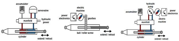
Pneumatic, Electric and Electro-Hydraulic Actuator
Within the field of electromechanical actuation the three main drive types are:
- Rotary
- Linear
- Geared
- Direct Drive
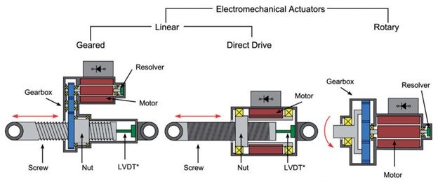
Rotary and Linear Electromechanical Actuators
The past 30 years have seen a trend toward electric actuators, especially in sectors such as aerospace and defence. Electric actuators offer many advantages
over the others including reduced mass, better reliability, and less support infrastructure, making them ideal for flight applications.
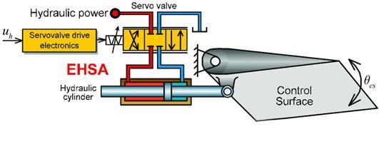
Electro-Hydraulic Actuator: Flight Control
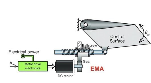
Electric Actuator: Flight Control
Control surface actuators produce the motion that adjusts the airflow over a vehicle or projectile’s flight surfaces. This causes the airflow over and around the surfaces to change, altering the forces on the flying object. These forces are used to control the direction and attitude of flight.
Electromechanical actuators use an electric motor to create the force/torque
required for this motion. There are many different electromechanical actuator designs that use AC or DC motors to produce rotary motion. Final output torque and speed are managed via a gearing system suitable for the specific application. It is possible to convert rotary motion into linear if linear actuation is required. The simplest way this can be done is by rotating a screw through a thread socket, but there are many other options to achieve the desired outcome.
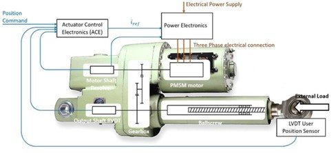
Typical Electro-Mechanical Actuator
Control surface actuators are present on almost everything that flies: including aircraft, unmanned aerial vehicles (UAVs), and missiles. They are used to control
the ailerons, elevators, and rudders of aircraft, and the control fins of missiles on instruction from the flight control computer.
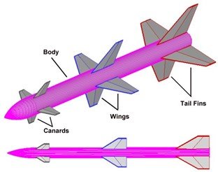
Missile Flight Control Surfaces
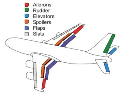
Aircraft Flight Control Surfaces
Choosing the Right Actuator
Design
There are many factors to consider when choosing a control surface actuator for a given purpose. The actuator must be able to produce enough force/torque to move the control surface and do so with the precision of motion required by the flight control computer.
Due to the technical challenges and constraints placed on actuators, there are many projects for which COTS actuators are unable to perform the required task. This is common in the realm of control surfaces since they are used in complicated designs where the consequences of failure could be devastating.
For projects like these, configurable actuator solutions deliver better outcomes, and allow the customer to enumerate extremely specific requirements and constraints. A configurable actuator is then designed and manufactured that can perform the required function under these constraints. Using COTS components can necessitate redesigns of surrounding parts or lengthy testing processes to determine the actuator’s viability. This significantly increases the time and money spent developing the product as a whole.
Discussed below are five key constraints that must be considered when developing custom actuators.
Space and Weight
In any actuator design the power-to-weight ratio is a vital consideration and has a direct impact on the performance of the vehicle in which it is employed. Most vehicles have weight limits that include both the hardware and payload. Reducing the weight of the hardware allows for greater payload mass. This could be used to carry extra fuel or additional passengers/cargo. When it comes to flying, weight equals money.
Most modern aircraft, be they UAVs or manned planes, incorporate many actuators. The effect of reducing actuator mass accumulates and can have a significant effect on the vehicle’s overall dry weight.
Another consideration is the physical space the actuator must fit into. Depending on the design of the vehicle or projectile this could be a major constraint. The actuator may have to be reorientated to ensure it can fit while still being able to complete its required task.
Given that space and weight are at a premium, designing an actuator system that can produce enough torque/force under these conditions presents a significant challenge, and is rarely possible using COTS options.
Environment
Control surface actuators are exposed to a wide range of temperatures and environments and must be able to supply the same force and precision across all conditions. At 40,000 feet, temperatures can drop as low as -50oC, whereas on the ground in desert climates, actuators can occasionally reach 100oC inside their metal housings.
A possible point of failure for an actuator operating at extreme temperatures is the method of lubrication used. Temperature affects the viscosity of the lubricant. The higher the temperature, the lower the viscosity, leading to thinner lubricating films on the gears and therefore greater friction. This has a detrimental effect on the
actuator’s performance and can even lead to failure.
At lower temperatures the viscosity of the lubricant increases. This can cause the lubricant to congeal, restricting its spread across all the required mechanical elements, and thus increasing friction in those areas. This build-up of lubricant can also result in high start-up torque. These two factors reduce the performance of the system and can potentially cause the actuator to fail.
Significant testing using different lubricants is required to ensure the actuator performs to specification requirements across the performance spectrum.
Shelf-life Requirements
A typical actuator is expected to have a shelf life of 25-30 years, assuming it is regularly exercised. Actuators must be run periodically to ensure the lubrication remains properly distributed around each machine element and does not congeal. This is fine for aircraft and unmanned aerial vehicles (UAVs) that are in constant use, but becomes a technical challenge for missiles which may sit idle for many years between servicing, and which need to function optimally as soon as they are called upon.
Missiles require bespoke actuators that can guarantee performance after years spent idle. This could mean the use of different lubricants or the application of lubricants via different techniques to stop them degrading over time.
To improve the shelf life of an operational vehicle or projectile, many designs incorporate plug-and-play actuators. This allows for one actuator to be swapped out for another without affecting the rest of the system.
Reliability
Control surface actuators must be able to reliably take control signals from the flight computer and convert those into accurate movements of the control surfaces. Failures by the control surface actuator can have dire consequences given the applications for which they are commonly used. The industry-standard lifespan for control surface actuators is generally 50,000 flight hours.
Depending on the application, there is significant variation in the amount of use a control surface actuator gets. UAVs may be airborne for 24 hours, whereas missiles have flight times measured in minutes or even seconds.
Would you like a copy of this White Paper?
If you would like to receive a PDF of this White Paper and are interested in actuation in the defence, aerospace and oil and gas sectors, give us your email address and we will keep you in formed of the latest news and innovations.
Sign up for the white paper and our email updates
Use Case: Missile Fin Actuator
Background
A leading international defence manufacturer came to OTM with an issue regarding a surface-to-air missile. The space in which the missile fin actuator had to be installed was small and exposed to high temperatures.
The customer had spent three years trying to solve this problem testing different
COTS actuators. The smaller the actuator, the less torque it can produce. Given the small space available, COTS actuators were not able to provide enough power to control the missile’s fins. The customer looked to OTM to configure their actuator solution to their needs.
Problem
The small space available to house the actuator lay between the rocket motor and the outer skin of the missile. The specification requirements were as follows:
- It had to weigh less than 2.75 kg whilst still providing 50 Nm of output torque and a bending moment of 230 Nm.
- The actuator had to operate in temperatures up to 120o
- The actuator had to offer a positional accuracy of 0.02o.
- Another key technical challenge was the shelf life of the missile. The missiles have a service period of 10 years, and post-installation access to the actuator would require major disassembly of the missile, making it impractical.
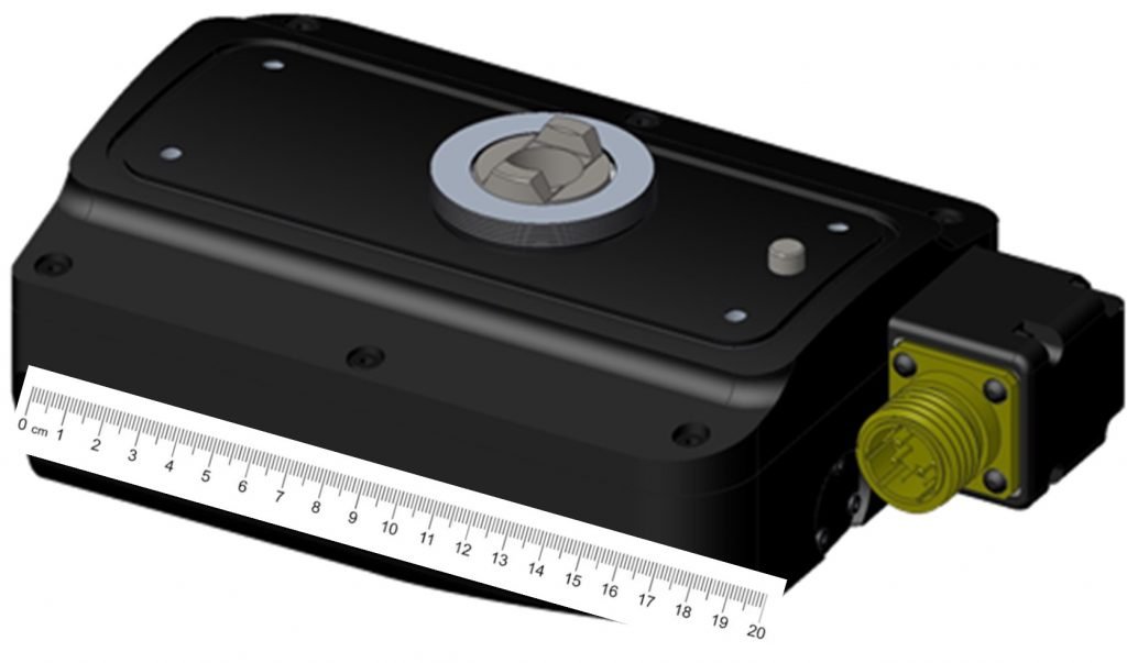
Compact Electro-Mechanical Missile fin Actuator
A typical actuator shelf life is 25-30 years but this assumes regular exercise or servicing to ensure the lubricant remains distributed around the machine components. For this project, the only tests that could be performed were electronic test sequences. The location of the actuator meant it would require excessive labour and time to disassemble the missile in order to gain access. Such maintenance is not practical when the missile is deployed in the field. An actuator exercise regime was not possible due to the above, so replacing the actuator was
not an option.
Producing an actuator that can meet all these requirements was a significant engineering challenge, but is exactly where a company like OTM excels. OTM pride themselves on designing and producing high-powered configurable actuator solutions that can operate within cramped spaces, harsh environmental conditions, and restrictive weight constraints.
Solution
To meet the tough spatial and power requirements, OTM thought ‘outside the box’. Most missile fin actuators operate in line with the motor. This was not possible given the small space available, so the actuator had to be rotated 90o to operate at a right angle with respect to the body of the missile. This configuration allowed it to meet the power-output requirements while still fitting between the outer skin of the missile and the inner cylindrical motor.
Producing an actuator that could function after 10 years in storage required an unorthodox approach to lubricating the gears. Over such a long period a conventional lubricant would separate and therefore could not be used. OTM
performed rigorous testing on different lubricants and methods for distributing them around the components. This involved experimentation until a solution was found.
OTM called upon experience from a previous design in which a set of gears were required to operate in a clean environment, yet still required lubrication. In that application, conventional lubricants would have been dispersed around the gearing area by the centrifugal force created by the rotating gears themselves. This would lead to unwanted contamination of the surrounding environment. Like the missile situation, ordinary lubricants would not suffice.
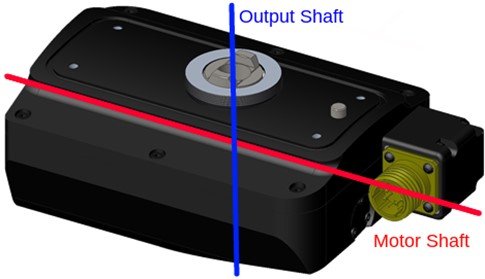
Compact Electro-Mechanical Missile fin Actuator
Using the knowledge gained from that situation, it was decided to try the same methodology to solve the lubricant problem in the flight control actuator.
After much experimentation, the answer was a lubricant that could be baked onto the surface of the gear teeth. This ensured the lubricant would not congeal over time and the actuator could perform after 10 years without use.
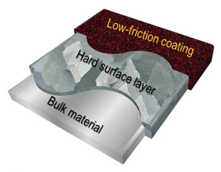
Experimentation Resulted in a Low Friction Coating Baked on to the Gear Tooth Surfaces
The Future of Flight Control Surface Actuators
Progression of Electro-mechanical Actuation
Of the three main energy sources used in actuation, there has been a growing trend towards electricity due to the significant benefits offered by electrom-echanical actuators.
The key benefits of electro-mechanical actuators are:
- Improved control of the motion profile compared to competing technologies. Software is used to give complete control over the velocity and position of the motion.
- They require less maintenance; this is important for minimising turnaround times for aircraft and can have a significant financial impact.
- They can provide greater power at lower mass compared to pressure actuators.
- An electro-mechanical actuator can produce the same power as a pneumatic actuator whilst being a quarter of the size. The improved weight and size properties make them ideal for aerospace applications.
- Electromechanical actuators can be self-contained units, allowing them to be used in simple plug-and-play situations.
Hydraulic and pneumatic actuators require extra equipment to direct their fluids, leading to more complicated installation processes. The high-pressure gasses and flammable hydraulic fluids can also present hazards which aren’t present in electromechanical devices.
Environmental concern is also a driving force behind the spread of electromechanical actuation. Every industry on the planet is looking for ways to eliminate fossil fuels and reduce carbon emissions. Not only does electromechanical actuation reduce the direct use of oil compared to hydraulic, but they are also more efficient.
With the refinement of higher-power electric motors and better energy storage, the aviation industry is looking towards all-electric aircraft. Within the aviation industry, the advancement of electric aircraft is regarded as analogous to where the electric car industry was 20 years ago. If it follows a similar trajectory, all-electric aircraft will soon become a major industrial segment.
Embedded Lightning Protection
Lightning protection is a significant safety issue for aircraft and UAVs. A large surge of current can damage electrical equipment throughout the airframe. This is especially important given the expanding use of electro-mechanical actuators.
The actuators must have lightning protection to ensure that lightning cannot disrupt their operation. This includes surge protection that arrests the maximum voltage across the actuator.
Since signal transmission is just as important as the actuators’ mechanical operation, it too has to be protected. Arguably the best solution is to use fibre optic cables to transmit the control signals from the flight control computer. Unlike copper wiring, fibre optic cables are not susceptible to the electromagnetic interference that can be caused by lightning.
Conclusion
For over 50 years, OTM has been at the forefront of actuator design and manufacture. OTM specialises in bespoke electromechanical actuation solutions that can provide high-precision movement under harsh spatial/weight conditions and extreme climates. The team at OTM have a vast range of experience and expertise in design, manufacture, and assembly. They use a flexible consultative approach to projects, allowing their technical problem-solving skills to shine.
Many companies believe a COTS actuation solution can save them money up front. However, this approach often leads to spending significantly more money and time during development, when they must modify their own components to fit with an actuator that is not right for their situation.
OTM believe the actuator should be designed around the technical specifications
presented by the client. They use a building-block approach to bespoke design, allowing clients to pick and choose the functionality they require. OTM has the experience to be able to cut short development cycles, delivering solutions that work right out the gate.
OTM’s tailored bespoke approach applies to every aspect of actuators including the communication interface. They can meet whichever protocol is needed, including RS 425, Canbus 825, and Mil Standard 1553, among others.
OTM sells products globally in many industries, including defence and aerospace. They have significant markets in India, Brazil, the UK, Europe, and North America.